Multirotor configuration
Now we have the firmware installed on the autopilot and the software installed on our computer to do the setup, we can start working through the mandatory hardware configuration and understand how to make parameter changes.
The ArduPilot developers have produced the ArduPilot Methodic Configurator which is aimed to semi-automate a clear, proven, and safe configuration sequence for ArduCopter drones. This is an extremely useful tool and you should familiarise yourself with it, but can be a little overwhelming for the first-time user who is unfamiliar with the ArduPilot system, so we will work through changing setting via Mission Planner in this lab.
Mandatory hardware
Mission Planner provides a logical list of >> Mandatory Hardware items (found on the SETUP screen) that need to be configured before the autopilot will work. This list includes:
- Frame type
- Initial tune parameters (delay this until after further setup)
- Accel calibration
- Compass
- Radio calibration
- Servo outputs
- Serial ports
- ESC calibration
- Flight modes
- Fail-safe
- HW ID - (information only)
- ADSB - (only if you have an ADSB out module)
Although these can be set via the parameter configuration pages (the CONFIG screen), it is sensible to step through them here in the logical order to ensure you complete them all.
Work through the Mandatory Hardware section of Mission Planner by following the below sections to complete the initial setup of the iron-bird.
Frame type
On this page you need to select the Frame Class and Frame Type to match the physical frame. In this lab the iron-bird is setup as a Quad class and X type.
All these sections are just user friendly ways to update the parameters for the autopilot. Here Frame Class relates to the FRAME_CLASS parameter and Frame Type to the FRAME_TYPE parameter.
A useful resource is the Motor order diagrams which show the motor order for each frame type. This shows you the vast number of frames available.
Initial tune parameters
In this section you are asked to set the propeller size and battery details. It is recommended to do this once all the initial setup is done and the battery monitoring is set and working. Therefore, we will return to this section later.
Accel calibration
Calibrating the accelerometers is mandatory in ArduPilot and cannot be performed while the vehicle is armed.
To complete this we first need to check that the AHRS_ORIENTATION parameter is correctly set (this parameter defines the direction the board is facing relative to the multirotor).
To do this we need to understand how to get, set, and update parameters via Mission Planner - this is a very common task when setting up and configuring an autopilot. Parameters define the functionality and configuration of the drone.
The full list of ArduPilot Copter parameters can be found here: ArduPilot > Copter > Parameters. Be sure to set the list to represent the correct version number of your ArduCopter. There are similar lists for Plane and Rover.
To view and change parameters:
- navigate to the CONFIG screen and select the Full Parameter List tab to view all the parameters.
- On the right-hand side, in the Search box type in the parameter you want to see or update. In this case it is
AHRS_ORIENTATIONextraThis search bar can take the wildcard entry
*. To try this, have a go a getting a list showing which RC channels are reversed, by searching forrc*_reversed. - Check which way the arrows on the autopilot are facing relative to the airframe and set the Value accordingly by selecting from the drop-down in the Options column. For this lab it should be set to None (which has the Value = 0).
- Once you have updated the parameter push the Write Params button on the right-hand-side and follow the prompts to complete the process.
With AHRS_ORIENTATION now confirmed return to the SETUP and Accel Calibration tab.
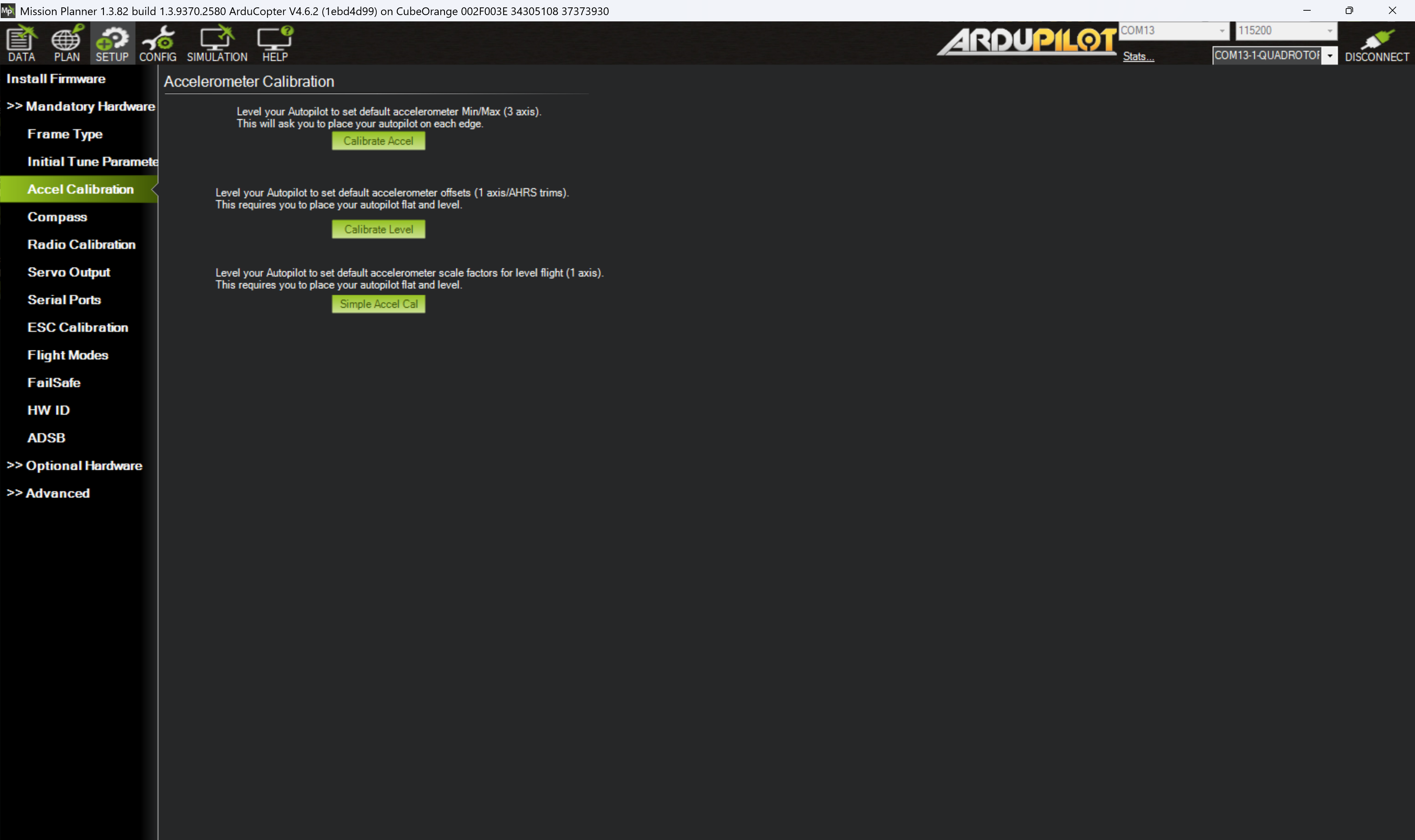
Figure 11: Mission Planner Accelerometer calibration page
Click Calibrate Accel to start the calibration procedure. During this the prompts will ask you to orientate the drone in each axis and then proceed to the next. This diagram can be useful for showing the directions if you are unsure.
The two most crucial elements of this calibration are:
- making sure the first LEVEL is as close to level as possible, and
- to keep the vehicle still immediately after pressing the button for each position. Being at the exact angle for the other positions is less important than being still.
Once complete the Mission Planner prompt should display "Calibration Successful".
The Calibrate Level can be used to recalibrate the level position trim (as long as it is within 10° of the full calibration). This can be useful to trim the drone's level flying attitude.
Compass
Compass calibration is another mandatory step for multicopters using a compass as the source for yaw and poorly calibrated systems can be the cause of many a headache and is a common reason for vehicle arming to fail. The process of completing a compass calibration can also be seen as a dance to the drone gods, the "compass dance". The Compass Calibration webpage gives some very useful notes and tips on how to best calibrate the compass.
It is important to have a good 3D GPS lock when the compass calibration is done. This usually means move outdoors to ensure a good GPS lock before doing the compass calibration.
For this lab, as part of SESA6084, we will complete the calibration indoors to show you the steps on the iron bird.
- Navigate to the SETUP screen and the Compass tab and observe what compasses (and how many) have been found and compare this to your setup.
note
The iron bird for this lab contains one internal compass in the Cube flight controller and one external in the Here3 module. Because we have not setup the Here3 module it is likely only the internal one is showing, therefore we will set up the Here3 now.
Here3 configuration
The Here3 GPS module communicates to the autopilot using the CAN bus therefore we need to updated some parameters to configure the software to work with the hardware.
- Make sure the four-pin connector from the GPS module is connected to the CAN1 (or CAN2) port of the autopilot.
- If the flight controller is not yet powered on then power it on and connect to Mission Planner.
- Go to the CONFIG screen and select the Full Parameter List tab.
- Using the search bar to find the parameters, modify the following to enable the GPS module:
CAN_D1_PROTOCOLto 1 (set the virtual driver of CAN1 to DRONECAN)CAN_P1_DRIVERto 1 (enables the CAN1 bus)GPS1_TYPEto 9 (sets the communication protocol type of GPS1 to DRONECAN)NTF_LED_TYPESto 231 (sets the bitmask of the notify LED to work on DRONECAN as well as a few other types)
- Click Write Params to upload the new parameter values.
- A reboot of the autopilot is needed to use the new CAN functions. There are two ways to reboot:
- Either physically power down the flight controller and then power it back up or
- Go to the DATA screen and on the Actions the top drop down contains a list of actions you can perform. Select
Preflight_Reboot_Shutdownand the push the Do Action button.
Restart your flight controller and just by looking at the LEDs on the Here3 modules, work out what status the platform is in. This RGB LED Meanings is a useful resource.
Compass calibration
Returning back to calibrating the compass:
- Return to the Compass tab on the SETUP screen
- Confirm you how see the correct number of compass modules (for the lab this should be 2, the internal one and the one we have just added from the external Here3 module).
- Reorder the compasses such that the external compass is marked as Priority 1.
info
The table in the Compass Priority section shows you other information about the compasses present such as the bus type: the Here3 communicates via the CAN bus (UAVCAN). You can also see the orientation of the compass relative to vehicle frame (to update this you have to do it via the Full Parameter List on the CONFIG screen).
- To perform the compass calibration click Start in the Onboard Mag Calibration box.
caution
Do not perform the calibration near any metallic or magnetic field producing objects (mobile phone, metal desks, power supplies, etc.) as this will produce an incorrect calibration. For this lab, although we are doing it indoors, you still need to ensure you are clear of any metallic or magnetic field producing objects!
- Once you have started the calibration process you need to hold the vehicles in the air and rotate it so that each side (front, back, left, right, top and bottom) points down towards the earth for a few seconds each turn.
- As the vehicle is rotated the green bars should gradually extend to the right.
- If the calibration is successful, then a “Please reboot the autopilot” window will appear. Complete the reboot.
- If the calibration is unsuccessful, then you may need to start troubleshooting.
info
A useful resources for troubleshooting compass issues are ArduPilot > Compass Calibration and ArduPilot > Advanced Compass Setup
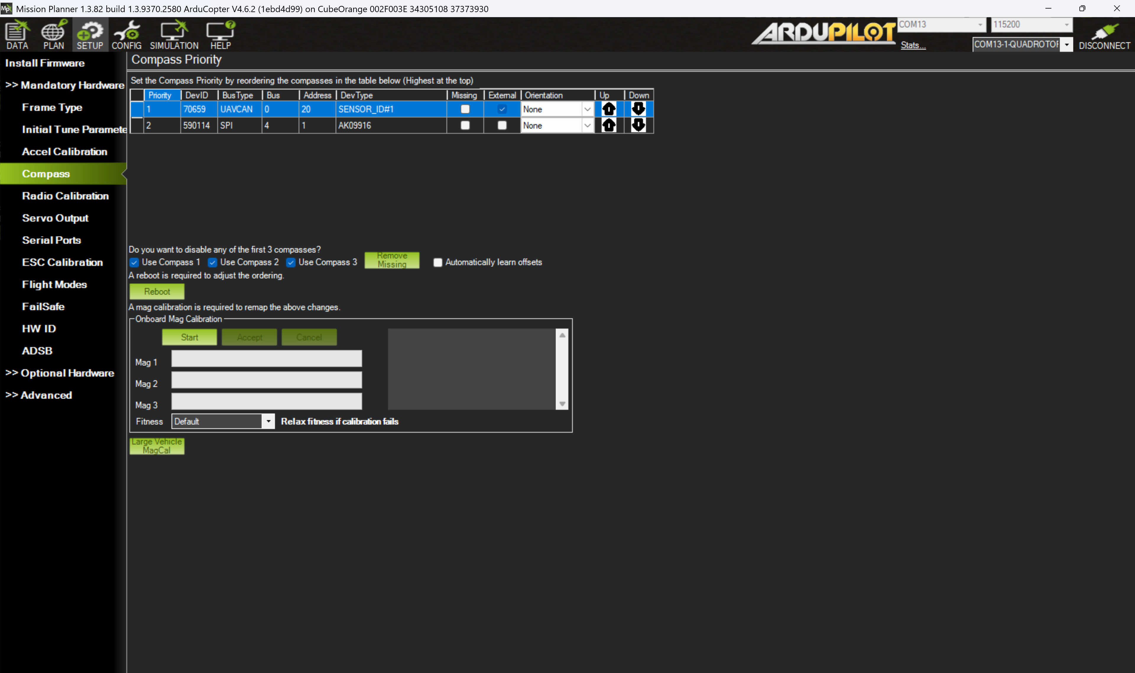
Figure 12: Mission Planner Compass calibration page
Once the compasses are calibrated correctly and the autopilot has been rebooted, check if the system is presenting any PreArm warnings. This can be checked on the HUD via the DATA screen, or in the Messages tab. Note down what they are, are any of them related to the set-up we have already done? (Have a look here for what they mean: ArduPilot > Copter > Pre-Arm Safety Checks)
Never arm the vehicle with the propellers on unless it is in a safe and remote location, and you are about to fly.
Radio calibration
So far, all the lab tasks have not required the transmitter to communicate to the autopilot. However, this is now the stage where you need to confirm the vehicle is correctly reading in the transmitters values and the channels are correctly setup.
The transmitter can be used to select flight modes, control the vehicles movement and orientation, run automation tasks, and perform auxiliary functions.
Binding transmitter and receiver
For a transmitter to communicate with a receiver they must be bound. This is achieved by putting both the receiver and transmitter into a bind-mode. Once they have recognised each other they will then be able to communicate.
In this lab the transmitter and receiver are already bound. This is because when a device is in bind-mode, it can be bound by any other device. Therefore, if all groups were to complete this task at once, there is a high likelihood that groups will bind transmitters and receivers randomly.
To find out how to bind the transmitter and receiver follow the instructions on their user manuals or datasheets:
To find out more about TX and RX protocols, a blog entry by Oscar Liang explains them well: Oscar Liang > RC Protocols and to find out which RC protocols are compatible with ArduPilot look here: ArduPilot > Compatible RC Protocols
It is best practice to set switches such that when they are away from you they are how you want the vehicle to power on (i.e. the safest mode and settings). Transmitters will often give you a “Switch Warning” if you turn the transmitter on when they are not in this position.
Once your transmitter is bound it is best practice to always turn your transmitter on first (check all switches are in their correct / safe positions) before you power on your vehicle.
Radio calibration
To check the transmitter is set up correctly power on your transmitter and look at the Radio Calibration tab on the SETUP screen to view the received signal values.
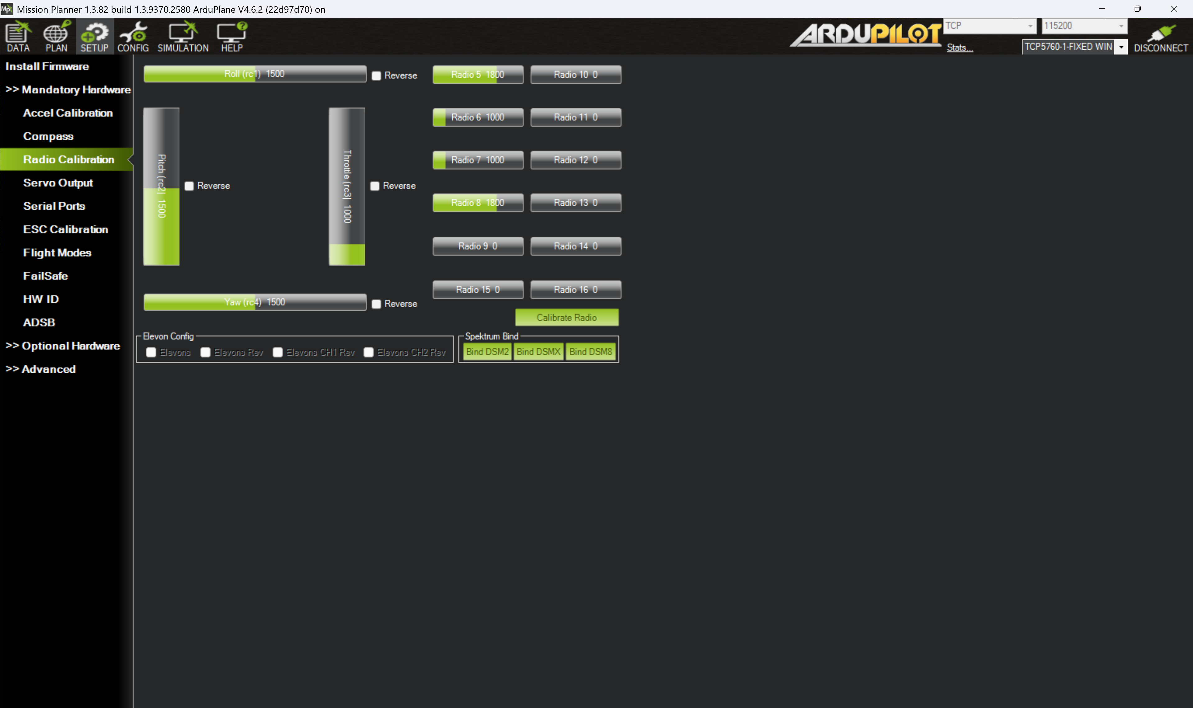
Figure 13: Mission Planner RC calibration page
Check the transmitter inputs (sticks and switches) and channel mapping is correct and make changes if required. Then perform a radio calibration by following the instructions provided in Mission Planner (click Calibrate Radio).
For help or more information about radio calibration look at the ArduPilot > Radio Control Calibration webpage.
Servo outputs
The Servo Outputs tab allows you to define which output port on the Cube Orange flight controller goes to which motor. For this lab we are configuring a quadrotor so expect to see four motors. The order should match up to the systems diagram shown in the Iron bird hardware page of these lab documents. You can remind yourself of the motor order diagrams to check the software configuration matches with the hardware configuration.
Serial ports
The Serial Ports tab allows your to quickly access the serial port settings available for your platform. It is common to use the first or second serial port for telemetry modules to the ground station. It is good practice to set the protocol of any unused serial ports to None.
Check out the CubePilot documentation on the serial ports to understand their specification and recommendations. The Cube Orange carrier board also contains an ADS-B in receiver, for details on how to set this up check out the ADS-B Carrier Board documentation.
Setup the flight controller to send ADS-B data to the ground control station using the options on the Serial Ports tab and Full Parameters List (note as the is no telemetry module on serial 1 in this lab, you just need to set SR0_ADSB to 2 and you can leave SR1_ADSB and SR2_ADSB as 0). Once updated and rebooted, see if any ADS-B data is received and displayed on the map.
ESC calibration
In some cases, the ESCs (electronic speed controllers) will require calibrating to the minimum and maximum PWM values the flight controller will send. This will ensure the ESCs have the correct throttle mapping.
To complete the ESC calibration you need to have completed the radio calibration setup first
Mission Planner has an in-built ESC calibration function found under the Mandatory Hardware section.
- To be able to perform this function we need to disable the safety switch by setting the parameter
BRD_SAFETY_DEFLTto 0 and then reboot the flight controller. (For more information about the safety switch have a read of this section) - Follow the instructions on the ESC Calibration window. In this lab treat the "battery" as the power supply provided.
- If this was successful, return the
BRD_SAFETY_DEFLTparameter to 1.
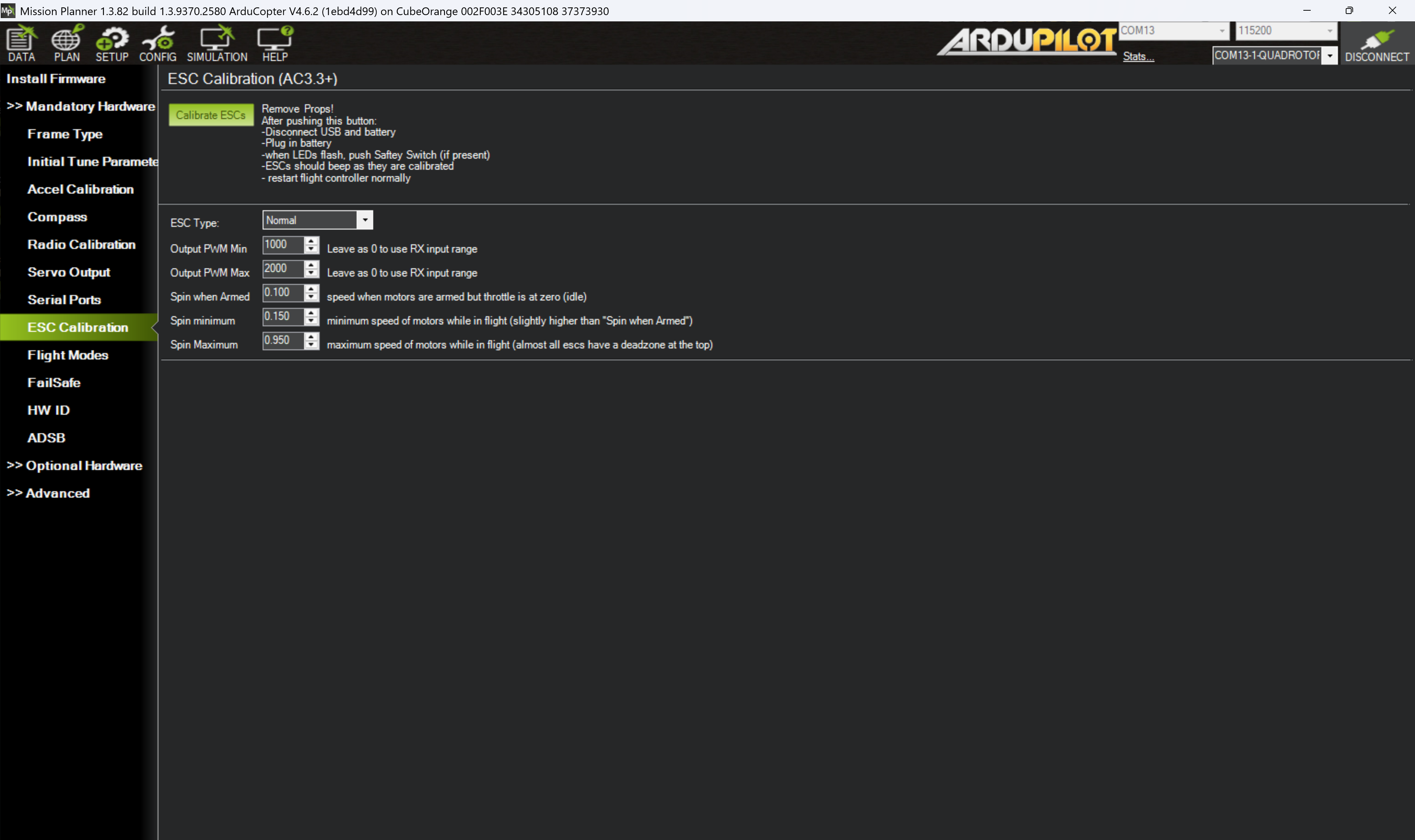
Figure 14: Mission Planner ESC calibration page
There is a chance than this in-built function does not work. If this is the case then try the all-at-once calibration method (although this is known to not always work too!).
Flight modes
Flight modes for multirotor vehicles are by default assigned to channel 5 of the transmitter. You can use the Radio Calibration tab to confirm which switch on the transmitter controls channel 5. You can change the assigned channel by updating the FLTMODE_CH parameter.
It is good practice to physically label your transmitter switches with their function (or, at the very least, document it).
To set the flight modes navigate to the Flight Modes tab and select the flight mode you wish to assign to each switch position. You can enable up to six flight modes controlled by the pulse-width modulation (PWM) ranges. The PWM range of each position is shown on the right-hand-side of the Flight Modes page. You can also update the flight modes in the Full Parameter List.
To find out what each flight mode does have a look at this resource: ArduPilot > Copter > Flight Modes.
Select a 3 position switch on the transmitter to control the flight mode and assign it three different flight modes (the first of which must be stabilised).
Fail safe
It is important to set up the vehicle such that, in the event of a malfunction, the vehicle fails safely. The autopilot has a number of failsafe mechanisms to ease the recovery and reduce the harm of a vehicle that has lost some form of control. These commonly consist of (note, not an exhaustive list):
- Radio failsafe – when the link between the transmitter and receiver is lost
- GCS failsafe – when the telemetry link between the GCS and the autopilot is lost
- Battery failsafe – when the battery voltage drops below a configured threshold
- EKF failsafe – when the autopilot has problems estimating the position of the vehicle
All these failsafe modes and actions are very important to set up correctly so you know how the vehicle will behave in such a situation. This can be done by looking at configuration settings for the autopilot and updating the parameters as required.
More information on the failsafe modes and actions can be found here: ArduPilot > Copter > Failsafe
Find the failsafe settings for a GCS telemetry loss of link. Set it to switch to RTL mode after 3 seconds of GCS timeout (and Land mode if there is no GPS signal) but only if the vehicle is not in a manual pilot mode.
The failsafe actions are means to reduce the harm should a failure occur (known as recovery controls in a bowtie risk assessment). You also need to be aware of means to prevent those failures from ever occurring (these are known as prevention controls in the bowtie risk assessment).
For more information about the bowtie model used by the CAA follow this link: CAA Safety Initiatives and Resources: Working with industry - Bowtie
The prevention controls put in place with this autopilot are known as PreArm safety checks. These check the system status (calibration, configuration, sensor data, etc.) before allowing the vehicle to arm. These checks help prevent crashes and fly-aways.
Never disable pre-arm checks without very good reason. They are there to help you find issues you may not have been aware of. Use this resource to help understand the checks recognise what is potentially causing the check to fail: ArduPilot > Copter > Pre-Arm Safety Checks
Battery monitor
Although it is not mandatory, setting up and enabling the battery monitor is extremely good practice. Having the knowledge of your battery’s status and health is critical to perform safe flights.
To set up the equipment on the iron-bird provided in this lab, complete the following steps:
- Under the SETUP screen and Optional Hardware section, select the Battery Monitor tab.
- Set the following parameters:
- Monitor to Analog Voltage and Current
- Sensor to 7. Cube HV Power Module
- HW Ver to 8. Cube Orange
noteIn the lab we are going to use a power supply to mimic a battery, but when you do use a battery, you should also set the Battery Capacity option to match your battery setup.
- Unplug the USB from the computer to reboot the flight controller, and this time plug in the power supply followed by reconnecting the USB to the computer.
- Reconnect the autopilot to Mission Planner and confirm that a voltage is visible on the DATA screen in the HUD or in the Quick tab (if setup to show battery voltage), and also under the Status tab.
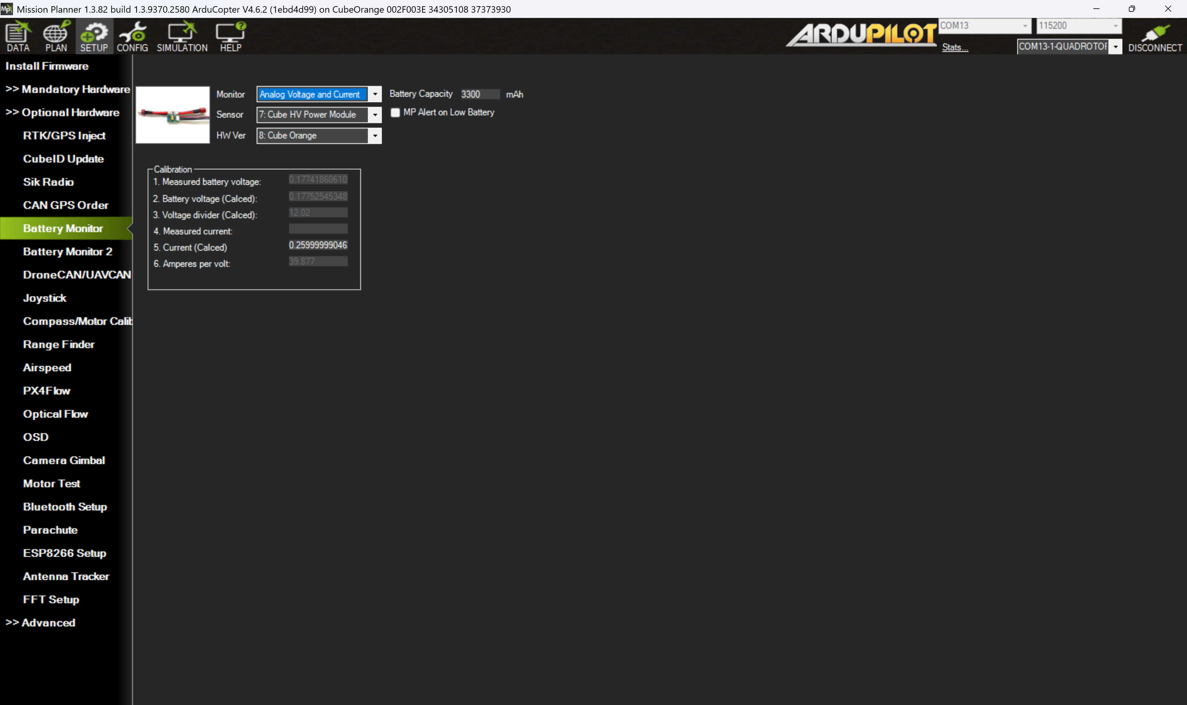
Figure 15: Mission Planner battery monitor page
Use a multimeter to update the measured battery voltage to give more acurrate readings.
Safety switch
The above step should of configured the flight controller to work. However, there is one more item to configure related to a safety feature of ArduPilot, the safety switch. The iron-bird does not have a physical safety switch installed - some GPS modules have a button but the Here3/3+ module does not. The switch toggles between two states: safe and unsafe. The safe state disables the outputs to motors and servos. Therefore we need to find a solution to operate motors and servos without a physical switch.
To confirm the flight controller is in the safe state, on the DATA screen the HUD should display the word SAFE near the horizon. This is also backed up but the PreArm message stating "PreArm: Hardware safety switch" which can be seen by either clicking on the "Not Ready to Arm" box on the HUD and looking at the PreArm messages in the pop-out window, or by going to the Messages tab and looking for "PreArm" messages.
There are three methods to switch the flight controller out of the safe state, the first two are recommended but we will use the third for this lab.
- Install a physical safety switch and use it.
- From the DATA screen, on the Actions tab, under the top dropdown menu select
Toggle_Safety_Switchfollowed by Do Action, and finally confirm you want to do this action in the pop-out window. This toggles the safety switch via software as opposed the a physical hardware switch. This is our recommended method where installing a physical switch is not an option. - This method uses a parameter to set the default state of the safety switch at startup, here we will disable it (i.e. the flight controller will start in the unsafe state allowing the outputs to the servos and motors to be enabled). Set
BRD_SAFETY_DEFLTto 0 and then reboot the flight controller.
Disabling the safety switch is not recommended and you should always try to include an external safety switch in your design or use the software safety switch to build in safety. This has only been done in this lab to simplify the lab tutorial.
Motor test
Now the firmware, additional sensors, and transmitter are all set up we can start to look at spinning the motors and confirm if they respond as expected. It is crucial to correctly match the motor direction and the physical position of the motor with the assigned motor number and the output channel.
Revist the hardware diagram and the ArduPilot motor order diagrams to confirm the hardware is correctly setup. If there are differences you can either
- fix it to match the documentation (recommended) or
- update the parameters to match the physical setup, then update your documentation!
To test the motors we will need to use the power supply to power the ESCs and motors. The maximum power rating of power supply is marginal for the iron-bird (for safety reasons) and therefore if too much power is requested the power supply will cut-out.
Never install propellers on motors unless you are about to fly
Ensure long hair, loose clothing, and unconstrainted wires are removed from the vicinity of the motor before testing.
Test the motors functionality and direction by following the instructions below.
To test the motors and directions:
- Ensure no propellers are attached and nothing can get tangled in the motor.
- Ensure the throttle stick is at minimum.
- On the SETUP screen and under the Optional Hardware select the Motor Test tab.
caution
The motors will be live when you push the “Test motor X” button. Ensure it is safe to spin.
- Test each motor in turn.
info
The motor letter-to-number mapping can be found here: ArduPilot > Copter > Quad Frames
- If the motor fails to spin, firstly check there are not any messages on the DATA screen. If there are no error messages (e.g. PreArm messages) then return the Motor test page and increase the
Throttle %input increments of 2 and test the motor again up to 15%. If the motor still fails to spin you might need to redo the ESC calibration. - Check the direction of the motors match the required direction.
- Once all motors are tested check the vehicle is disarmed by looking at the text in the HUD
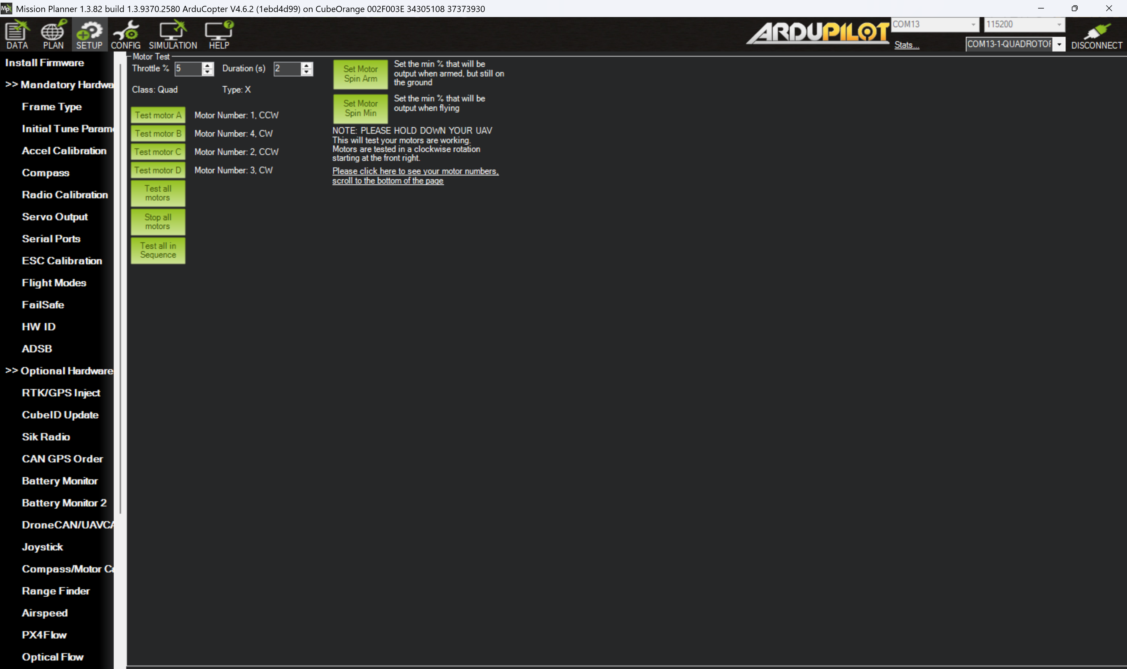
Figure 15: Mission Planner motor test page
To correct for a motor spinning in the wrong direction you need to swap any two of the 3-phase wires between the ESC and the motor. This will reverse the direction. Some ESCs also have programmatic ways to reverse the direction (either through the manufacture’s software or hardware).
For more information about brushless DC motors see the following resource from MathWorks: MathWorks: Introduction to brushless DC motor control
Initial tune parameters (revisited)
Now we have completed the prerequisites for the initial tune parameters (frame settings, calibrations, battery monitoring, and motor tests) we can return to the >> Mandatory Hardware Initial Tune Parameters tab and calculate the initial parameters by filling in the required fields.
Complete the initial tune section based on your knowledge of the system you have just comfigured and select the option "Add suggested settings for 4.0 and up (Battery failsafe and Fence)?". Click Calculate Initial Parameters and have a look at the suggested changes. Do you understand what they mean before you accept them and write them to the flight controller? If not, then find out what they mean.
To find out more about the initial parameter settings and tuning look at the ArduPilot > Copter > Tuning process instrucitons
Next
You have now completely configured the iron bird. The next section provides you some tasks to help you explore Mission Planner and become familiar with it and its features.