The iron-bird hardware
In this lab you are provided with a multirotor iron-bird that contains the autopilot and the other essential components for a multirotor, along with a basic transmitter and power-supply.
In aviation, the term iron-bird refers to a ground-based test device used for prototyping and integrating aircraft systems during the development of new aircraft designs.
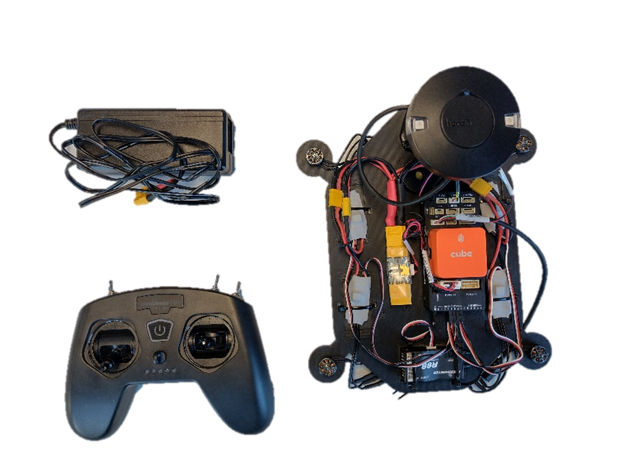
Figure 1: The autopilot lab iron-bird, basic transmitter and power supply
The iron-bird consists of six components that are required to create a basic functional multirotor. These components are listed below and expanded on in the following sections:
- Autopilot
- Receiver
- Electronic speed controllers (ESCs)
- Motors
- Power module
- GPS and external compass
- Buzzer (non-essential)
A simple system diagram, shown in Figure 2, highlights the integration of all these components.
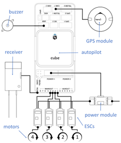
Figure 2: Iron bird system diagram
Familiarise yourself with the hardware on the iron-bird and its function by comparing the hardware to the system diagram above and by reading through the remaining sections.
Interactive overview
Use the interactive overview below to familiarise yourself with the hardware in front of you.
Autopilot
The autopilot used in this lab is a CubePilot Cube Orange, see Figure 3. For more information on this autopilot see docs.cubepilot.org. This autopilot has been selected due to its reliability (which has been established throughout the hobbyist and commercial sectors), its documentation, and its configurability.
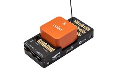
Figure 3: CubePilot Cube Orange autopilot
This autopilot consists of three IMUs, an onboard compass, two barometers, dual power input, dual external I2C, power monitoring, input and output ports, and two CAN Bus interfaces.
For more information on the systems within the autopilot, see the following resource: CubePilot > The Cube > Introduction> Specifications
Receiver and transmitter
The receiver used on the iron-bird is a Radiomaster R88 V2 receiver, see Figure 4. This receives the inputs from the transmitter (the controller that captures the inputs from the pilot, also shown in Figure 4) and sends them to the autopilot via SBUS signal protocol. The transmitter used in this lab is the basic Radiomaster T8 Lite transmitter.
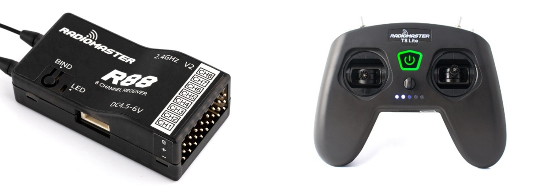
Figure 4: The Radiomaster R88 receiver and T8 Lite transmitter
Electronic speed controllers (ESCs)
The iron-bird is set up to represent a quad X configuration and therefore has four motors, which each need an electronic speed controller. The ESCs on the iron-bird are T-Motor AT 12A speed controllers (note that these are designed for fixed-wing drones, however they are appropriated for this application on the iron-bird) and can be seen in Figure 5.
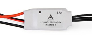
Figure 5: T-Motor AT 12A ESC
Motors
The motors on the iron-bird are T-Motor F1103 8000KV motors as shown in Figure 6. These are used in this lab to complete the hardware set up and to confirm if the autopilot (and wiring) is correct. If correctly set up they should spin when commanded, and in the right direction.
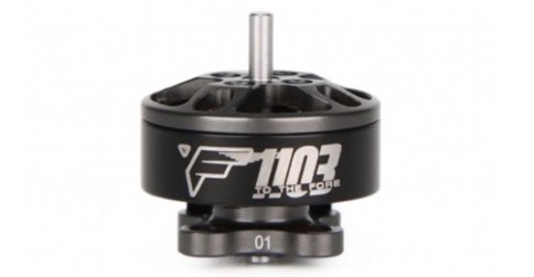
Figure 6: The T-Motor F1103 8000KV motor
Power module
To provide power to both the autopilot and the motors, the iron-bird uses the CubePilot Power Brick Mini. This passes the high current power from the battery/power-supply to the ESCs through a voltage and current monitor. It also acts as a battery eliminator circuit (BEC) and provides low current 5V power (and the data from the voltage and current sensor) to the autopilot.
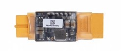
Figure 7: The CubePilot Power Brick Mini
GPS and external compass module
The iron-bird is equipped with a Here3 GPS module. Although a GPS sensor is not essential to have on a multirotor, it is a common sensor to use and important to know how to configure. In some cases, the autopilot software may require the external compass to be calibrated before allowing the motors to spin.
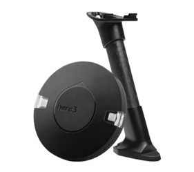
Figure 8: The CubePilot Here3 GPS module
Buzzer
The buzzer, provided with the CubePilot Cube Orange autopilot, provides two main functions. Firstly, it allows you to have an audible confirmation of actions performed (for example, arming the motors). This can be useful feedback to the operator or other parties as to the status of the multirotor. The second function is to provide an extension to the USB port, allowing you to compactly integrate the autopilot within the drone structure, but still access the programming USB port.
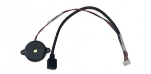
Figure 9: USB extension and buzzer cable
Other components
There are several other components that can also be used to compliment the vehicle that have not been included on this iron-bird. One important item is a telemetry transceiver. This allows messages to be sent and received to the autopilot. In the case of this lab you are going to use a USB cable in place of this (this removes the risk of radio cross-talk between groups which is common when operating several telemetry modules close together).